I’ve recently been playing with the keyboards of some of my old 80s computers for no reasons other than trying to understand how they work.
After a total failure with an Atari ST keyboard, I picked up an Acorn Electron I had marked with “flaky keyboard” to fix later. The Acorn Electron (nicknamed “the Elk”) was a weird machine, that I had when I was but a sprog, it was a cheap version of the BBC Micro with a lot of compromises made in its manufacturer to bring the costs down.
One area it didn’t skim on though was the keyboard. The keyboard uses proper switches and has a nice feel for typing on, especially compared to the horrors on the Spectrum membrane and rubber keyboard (and even the later versions of the Spectrum which used keycaps still had a membrane which made it all feel quite spongy.)

So how does the keyboard work? Taking a keycap off shows a switch underneath which isn’t helpful. Undoing the four screws that hold the Electron together shows a ribbon cable with a 22 pin connector, this will make it easy to use standard, cheap 2.54mm cables to connect it to something.
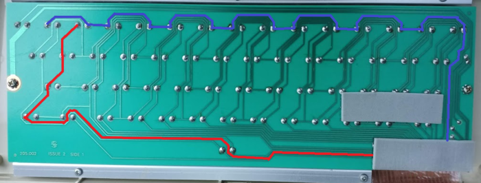
Having a look at the underside of the keyboard shows the circuit, badly highlighted in MS Paint below. As we can see, the red line links one side of four switches together, whilst the bluey-purpley line links the other side of 14 different switches. This makes a simple keyboard matrix.

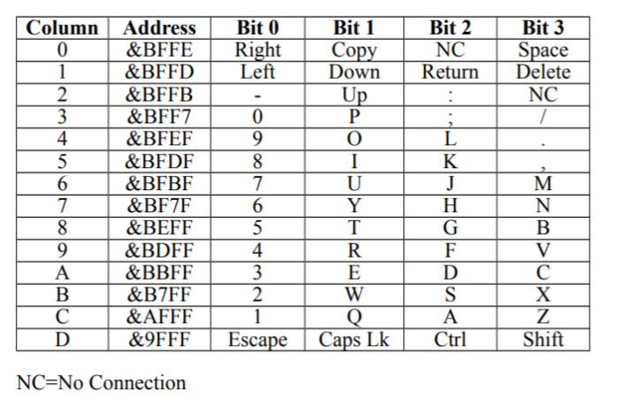
In fact a quick search of the Electron Advanced user guide shows up the keyboard matrix on page 218. We can see here that each column (i.e. 14 entries) is matched to a physical address.

Search for the engineer’s diagrams of the Electron shows that the pins go directly into the Electron’s ULA – a custom chip which manages most of the hardware. With the column lines labelled as address and the rows labelled as data. There are four other pins: Vcc (+5 V), Ground (0 V), Caps and Reset. Caps lock is the on and off status for the on keyboard Caps Lock LED, whilst Reset is the break key (presumably this mapped separately so that the computer can be reset if something messes with the keyboard buffer).

Using this and other sources on t’Internets shows the pinout of the keyboard connector is below with pin 1 being closest to the Escape key.

Right, so can we read a keypress? As the keyboard uses 5 V for logic I can’t use a Raspberry Pi without risking burning it out and an Arduino Uno doesn’t have 20 digital pins, so I got myself an Arduino Due clone and rigged up a custom cable between the Due and the Elk.
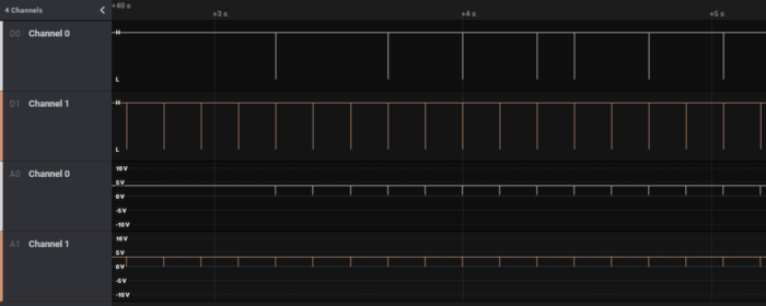
Performing a simple sniff (on one address line and one data line which mapped to the ; key) using a trusty Saleae logic analyser made it look a bit like I had a grounding error. If I pressed the ; key then I would see semi-regular spikes low on both the address and data lines. But, the address line would pulse low on a regular basis and the data line would exactly match the address line. So, what if I pulled the address line low.

I tried this and got… nothing, bugger all, not a sausage.
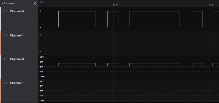
I spent about two hours swearing at this point, until I looked back at the results and noticed that the high voltage was about 3.7 V – the pins were floating – i.e. they hadn’t been forced to a set value. Looking back at the circuit this obviously wasn’t enough to trip the switch. The Arduino has an inbuilt resistor that can force an input to high, using INPUT_PULLUP instead of INPUT. So I tried again with the following program:
void setup() {
   Serial.begin(115200);
   pinMode(26, INPUT_PULLUP);
   pinMode(40, OUTPUT);
   digitalWrite(40, LOW);
}
void loop() {
}
This was much better and showed both the address line and data line showing a low status when I pressed the key.

Right, I have enough to turn this into a keyboard. The basic logic is to force each address line to low; then read each data line, if the line is low then set a bit for that data line; then set the address line to high; repeat through all address lines.
The code is a bit clunky and doesn’t do any press-release logic or look for key bouncing, but allows a key press to be recorded. My code can be found on Github. I managed to make some mistakes on my custom cable, so I had to manually mangle the pins in the program.
What use is this? Probably none, I could use this to convert the Elk keyboard to a USB or PS/2 keyboard, but this has already been done. The greatest potential use is that the code could be updated to create an Elk keyboard tester to test the keyboard in isolation.